Linking Controls
When a control component is drawn or added to the Limelight Interface Architect's display grid, it is disassociated with any real-world hardware (or anything else at this point other than iteself). It is simply a control that can be tied to various end-point properties or other controls. There are several ways to accomplish this as shown below.
- Component Linking - this method allows controls to affect other controls
- Property Linking - this method allows values of properties to be reflected and update by displays and controls
- Attribute Linking - this method is primarily used for touch screens (or mouse dragging) where a component with attributes is dragged and dropped on top of another control to set the target control's properties. This only can occur when deployed to the Display Client or in preview or full screen mode in Limelight Interface Architect.
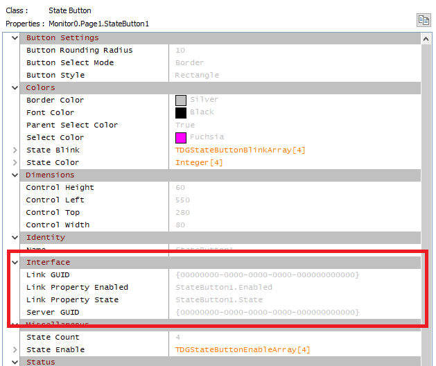
Every display grid component has properties for linking. The first primary properties are the Server GUID and the object Link GUID. The GUID or Global Unique Identifier is a 128 bit number that uniquely identifies an endpoint object within the Limelight XE universe. With these two IDs any server and object can be referenced. Once that reference is made, then the link properties can be established. The link properties are unique to each control type and follow the format "Link Property XYZ" where "XYZ" is the property name of the control that is being linked. Not all properties are exposed so only the primary properties can be changed by linking to a Limelight XE server (more on this in later chapters).
For example a State Button Control has both the Server GUID and object Link GUID properties, but it also has two additional; the Link Property State and Link Property Enabled properties which are strings. When using component linking, the link properties use "dot" notation similar to Javascript or C++ to access an object within another object. By default, both of these properties point back to themselves so the control will change state without being connected to another object (see below).
State Button Object Linking Properties
Component Linking
When both the Link GUID and the Server GUID are all zeros (default), the control is in Component Linking mode. This allows the properties to connect to other controls within the same display client (or test within Limelight Interface Architect). In this mode, the control can be tied to other controls via their path. The path of any control is shown above the property editor (the above example is "Monitor0.Page1.StateButton1"). To access a specific property, the property name is appended at the end. You can can also truncate the path if there is only one monitor or one path. For example, if there is only one monitor, the path can be simplified to "Page1.StateButton1".
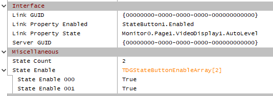
An example of direct component linking would be to use the above State Button to connect to a video display component to control whether the image enhancement is turned on or off. State buttons can have up to 16 independent states (0-15). The "AutoLevel" property only has 2 states; 0=off, 1=on. So first, we set the StateCount property of the State Button to 2. This will give us a toggle button that will switch between 0 (off) and 1 (on). Next we need to connect the button to the video display component. This is done by setting the Link Property State property to "Monitor0.Page1.VideoDisplay1.AutoLevel".
Connection to Video Display Component AutoLevel property on Monitor 0, Page 0
Once this property is updated, putting Limelight Interface Architect into Preview Mode (F2) or Full Screen Test Mode (F11) will allow the video feed to be toggled between raw and enhanced video simply by pressing the State Button.
Property Linking
When direct control of server properties is required, a control must be linked directly to the server and server object's GUIDs. This is accomplished by setting the GUID of the server and the target object's Link GUID. A simple way to do this is to log into the Limelight XE server from Limelight Interface Architect (all objects will be downloaded and appear in the Server Objects tree view) and follow this procedure:
- Click on the control you wish to link (it will be highlighted with a box around it).
- Click the target object in the Server Objects tree view (note the Link Tool is now enabled on the ribbon)
- Click the Link Tool on the ribbon in the Tools group of the HOME tab (note that the Link and Server GUIDs are now set to target that object).
Next, you need to set which property the component will control or monitor (or both). As above, the "Link Property" is the name of the object's property with no spaces. The Limelight XE server has the ability to automatically convert different property types between the display grid component and the actual hardware property type. For example, if you set a Dial Indicator Control's "Link Property Value" property to a Global Variable and set that value to something other than a number (e.g. "ABCD"), the control will show zero (0), but as soon as you update the value to a valid number (e.g. "1234"), the indicator will convert the string to a numeric value and display the result accordingly.
This is also true of boolean and other enumerated type values as shown in the Component Linking example above. Enumerated types will follow the order in which they appear. For instance, the boolean enumerated type is false=0, true=1. For another example the Video Display component's aspect ratio setting has 7 selections, so it would convert SDTV=0, Academy=1, IMAX=2, Monitor=3, HDTV=4, Wide Screen Cinema=5 and Custom=6. If you linked a state button with 7 states (0-6) to that property, an operator could continuously press the button and cycle through all the aspect ratios. This is just a small sampling of what is possible using both component and property linking.
Attribute Linking
Attribute linking uses the "Attributes" property of a control to carry additional information when an object is dragged over and dropped onto other controls. This is useful when you want a modern drag and drop touch control system where drawings of an object can also contain information about it. For example, a designer can draw a group of hexagons using the drawing tool (which has a hexagon tool), label them with object IDs (e.g. 1, 2, 3) and set the attributes to what ever they represent such as geolocation data. Once deployed, an operator can drag these hexagon shapes on to a map control and the map will automatically change to center on the location provided in the attributes property.
The attribute data is formatted JSON name / value pairs. The property has a dedicated editor for managing the correct JSON format and it will verify the format. Any name / value pair can be inserted into the Attributes property. Here is an example for geolocation data.
{
 "Latitude": 27.5,
 "Longitude": -80.3,
 "Zoom": 12
}
Attribute JSON Code Editor Dialog
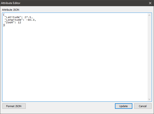
The attribute editor is launched by clicking the button located on the right of the attribute property (to the right of the attribute value) in the property editor.